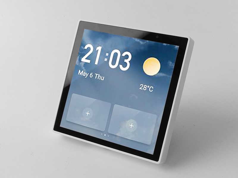
GS-T3E ~
Models~
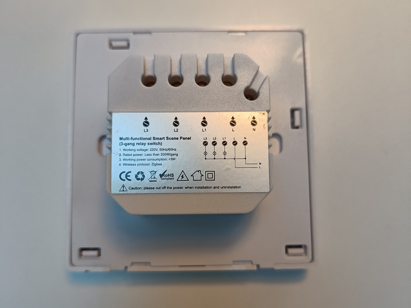
- EU model: 3 gang relay switch
- CN model: 4 gang relay switch
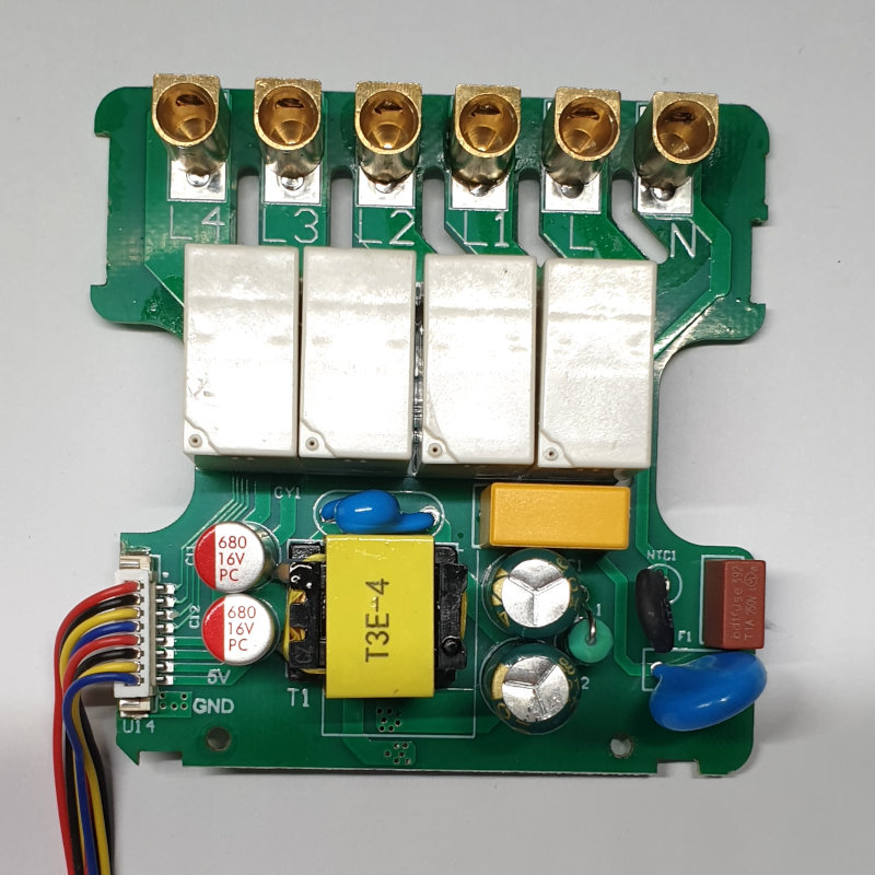
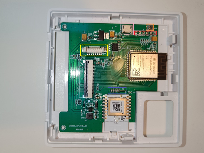
The PCB revision v2.3 (20221205) and v2.4 (20240909) is known to work with openHASP. Specify that you want the new device with PCB revision v2.3 or above when ordering from known vendor Golden Security on Alibaba.
Warning
Do NOT buy PCB revision v1.23 (20220817) because the internal antenna connector is NOT soldered onto the board.
Those devices will have no WiFi reception on the ESP32! This version is now discontinued, but some sellers might have old stock.
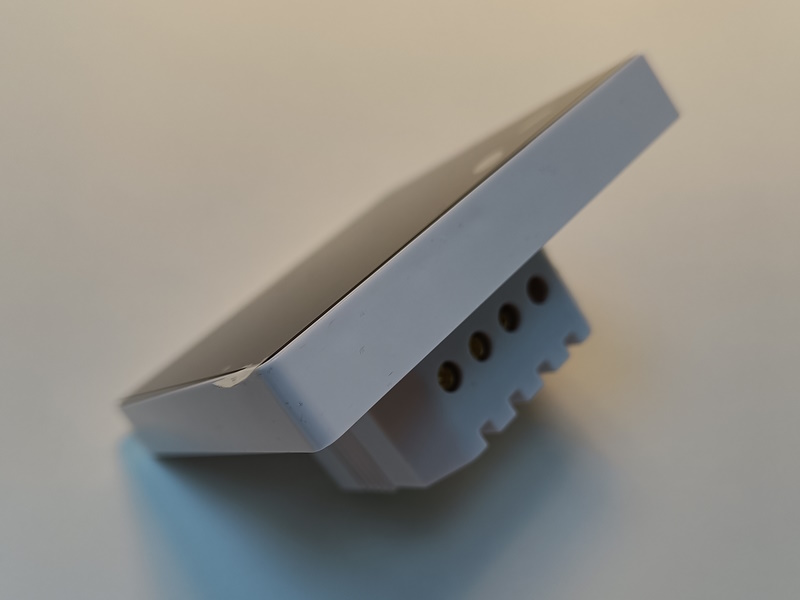
Form factor~
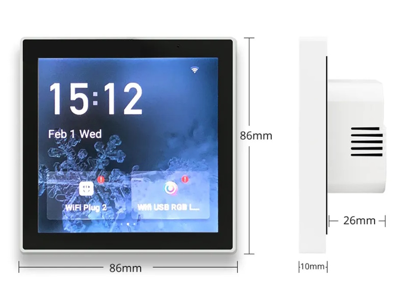
- EU model: 86mm x 86mm
- CN model (4-gang): 86mm x 86mm. Rear socket size: 70mm x 70mm x 26mm.
Maximum load is 200W per gang, 600W in total EU version.
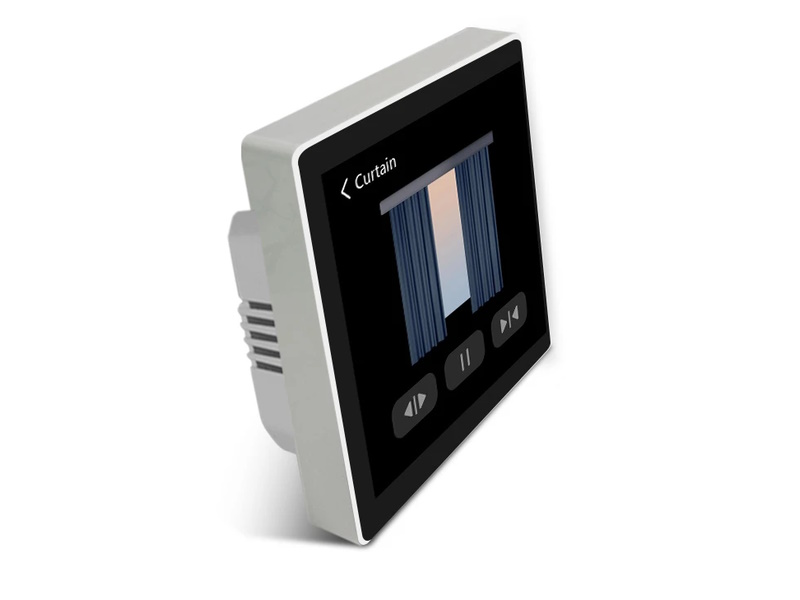
The models have the same recessed housing sliding into the wall, sized 50x50mm, with rounded corners creating a diameter of about 59mm. This makes them suitable for both EU and UK wall fixtures. The EU model fits in a properly deployed, standard 60mm round wall box and can be fixed with two side screws (use the screws which belong to the box instead of the ones shipped with the device).
The 4-gang CN model has a larger recessed housing, sized at 70x70mm with a depth of around 26mm. The two mounting screw holes are 60mm apart. This requires a larger hole in the wall to mount it.
Features:~
- Input voltage 110-250V ~ 50-60Hz AC
- ESP32-S3-WROOM-1 (Xtensa-LX7 dual core 240MHz)
- 8 MB PSram - Octal SPI
- 16 MB flash - Quad SPI
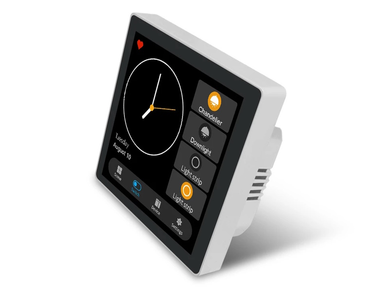
- Capacitive GT911 touch screen
| Pros | Cons |
|---|---|
| 8 MB flash | Tuya device with ZS3L Tuya chip on PCB (unused) |
| 16 MB PSram | Flash header pins not populated |
| 480x480 HD IPS LCD | |
| Capactitive touch | |
| Built-in PSU | |
| Standard wallmount form factor both EU and UK |
Note
openHASP does not support the proprietary Tuya chip, but you can still flash the firmware and use the other GS-T3E features just fine.
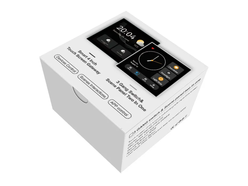
Packaging~
Flashing~
Disclaimer
Never connect high-voltage when the panel is not properly secured in place.
Device can be flashed by either using the USB port or the flash header pins and a FTDI serial programmer device.
Steps to flash via USB:
- Disengage the panel from high-voltage power
- Detach the panel from the PSU power supply
- Connect a Micro USB cable
- Connect
IO0toGNDto activate flash mode! - Press the
KEYbutton to powercycle (RESET) the board
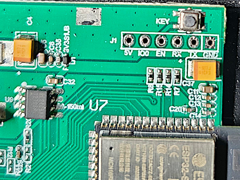
Steps to flash via UART:
v2.3:~
- Disengage the panel from high-voltage power
- Detach the panel from the PSU power supply
- Connect jumper wires:
- GND <--> GND
- 5V <--> 5V
- RX <--> RX (not reversed!)
- TX <--> TX (not reversed!)
- Connect
IO0toGNDto activate flash mode! - Press the
KEYbutton to powercycle (RESET) the board
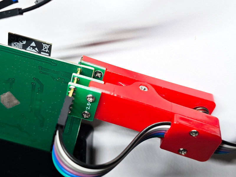
v2.4:~
v2.4 does not have a USB socket. Flashing can be done through flash header PCB holes, by soldering, or using a 2.54mm 6-pin single row pogo pin clamp tool.
Connections from PCB to serial programmer: - GND <--> GND - 5V <--> 5V - RX <--> TX - TX <--> RX - IO0 <--> GND to activate flash mode
Once the connections are made, flash the GS-T3E ESP32 binary like on any other device.
GPIO Settings~
3-gang EU version GS-T3E~
| Pin | Mode | GS-T3E | Group | Default |
|---|---|---|---|---|
| 45 | Output | Relay L1 | 1 | Low (Normal) |
| 46 | Output | Relay L2 | 2 | Low (Normal) |
| 44 | Output | Relay L3 | 3 | Low (Normal) |
Tip
To configure the GPIOs as light switches at once for GS-T3E send to topic hasp/<nodename>/config/gpio a message with payload:
1 | |
1 | |
Example jsonl
To create a page displaying the local relays as switches, try this very simple pages.jsonl:
1 2 3 | |

4-gang CN version GS-T3E~
| Pin | Mode | GS-T3E | Group | Default |
|---|---|---|---|---|
| GPIO1 | Output | Relay L1 | 1 | Low (Normal) |
| GPIO2 | Output | Relay L2 | 2 | Low (Normal) |
| GPIO46 | Output | Relay L3 | 3 | Low (Normal) |
| GPIO45 | Output | Relay L4 | 4 | Low (Normal) |
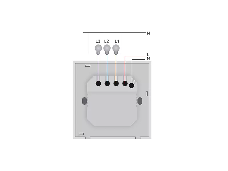
Wiring Diagram~
The switch supports this wiring configuration:
Warning
Always follow the instructions from the installation guide and local safety regulations. Consult a licensed electrician when changing your electrical wiring.
Product Video~
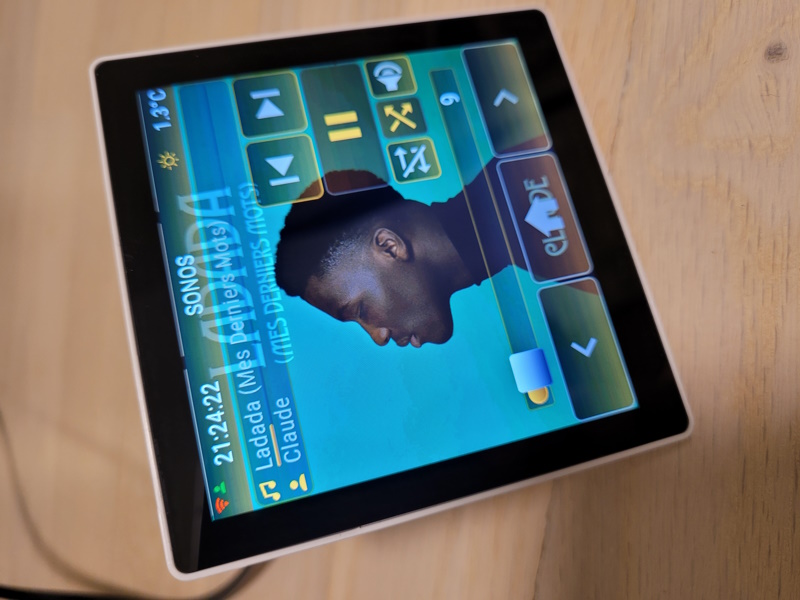
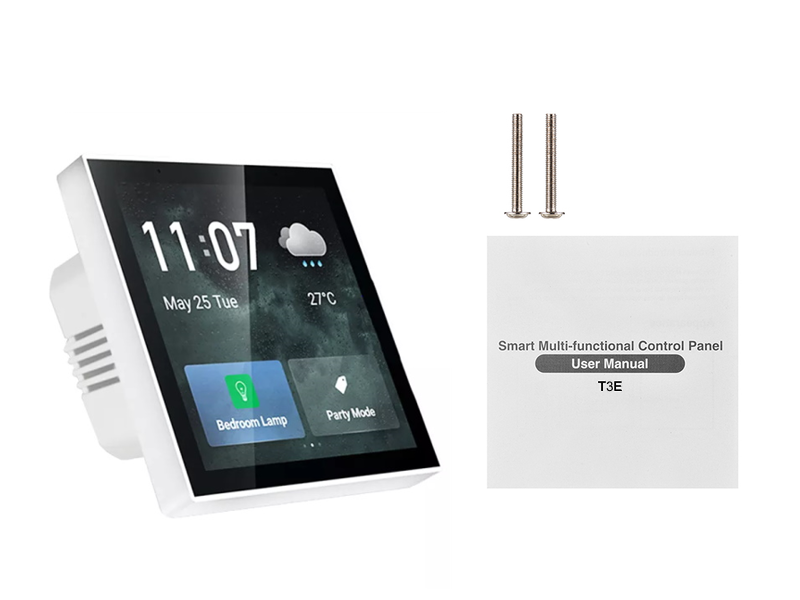
Gallery~